
Switching and VLANs
VLANs are one of my favorite tools in networking, and also the quiet source of a lot of "weird" problems. At the simplest level, a VLAN turns one physical switch into several separate networks. In real life they're everywhere: separating phones from laptops, carrying multiple Wi-Fi networks to an access point, handing off ISP circuits, keeping hosting customers apart, and connecting VMs to the right networks.
On this page
How switching works
A switch forwards frames based on destination MAC address. Every time a frame comes in, the switch writes down the source MAC and which port it came from. That's the MAC address table (sometimes called the CAM table), and it's how the switch learns where everything is.
| Traffic | What the switch does |
|---|---|
| Known unicast | It knows where the destination is, so it sends the frame out just that port. |
| Unknown unicast | It doesn't know yet, so it floods the frame out every port in that VLAN. |
| Broadcast | Floods to every port in the VLAN. |
| Multicast | Floods, or if IGMP snooping is on, only sends to ports that asked for it. |
Each VLAN gets its own learning, so the same MAC address can show up in two different VLANs without any conflict.
You'll also see switches described as store-and-forward (receives the whole frame and checks it for errors first, which is what most switches do), cut-through (starts forwarding as soon as it reads the destination, which is faster but can pass along broken frames), and fragment-free (somewhere in between, mostly a leftover from the days of hubs and collisions).
VLAN basics
A VLAN is a layer 2 network that doesn't care about physical layout. Two ports in VLAN 20 can talk like they're on their own little switch. A device in VLAN 30 can't reach them unless a router lets it.
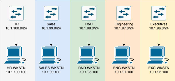
Without VLANs, you'd need a separate physical switch for users, servers, phones, cameras, guests, and management:
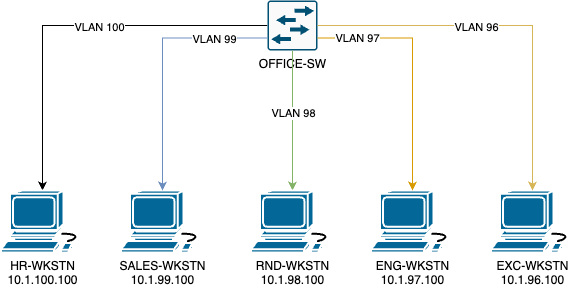
With VLANs, one managed switch does the job:
VLAN numbers
The VLAN ID is 12 bits, so 4,096 values. VLAN 0 and 4095 are reserved, leaving 1 through 4094. Some platforms reserve a few more on top of that.
I avoid VLAN 1 for anything real. It's the default on most switches, so stuff ends up there by accident. Create named VLANs and put every port where it belongs on purpose.
Why bother
- Isolation: separate broadcast domains.
- A place to put security: traffic between VLANs has to cross a gateway where you can filter it.
- Containing broadcasts: one chatty segment doesn't bother the others.
- Flexibility: group devices by what they are, not where they're plugged in.
- Sharing hardware: multiple departments, customers, or services on the same switches.
Tagging and trunks
An access port carries one VLAN and sends normal untagged frames to whatever is plugged in. The device doesn't even know VLANs exist. A trunk carries lots of VLANs by adding an 802.1Q tag to each frame so the other end knows which VLAN it belongs to.
Access port                         802.1Q trunk
+----------+      untagged      +--------+  VLAN 10 tagged
| Computer |---------------------| Switch |=================
+----------+                     +--------+  VLAN 20 tagged
                                               VLAN 30 tagged
The tag holds the VLAN ID plus a priority value. Switches, firewalls, routers, hypervisors, and access points all read it to drop the frame into the right network.
Kinds of ports
| Port type | What plugs in | How it handles frames |
|---|---|---|
| Access | Desktop, printer, camera, plain server | One VLAN, untagged |
| Trunk | Another switch, firewall, router, hypervisor, AP | Many tagged VLANs, maybe one untagged native VLAN |
| Voice + data | An IP phone with a PC plugged into it | Untagged data VLAN, tagged voice VLAN |
| Provider handoff | A customer circuit, or a link to another carrier | One or more explicitly tagged service VLANs |
A basic Cisco setup
! Create and name VLANs
vlan 10
 name USERS
vlan 20
 name VOICE
vlan 30
 name SERVERS
vlan 999
 name UNUSED-NATIVE

! A user access port
interface GigabitEthernet1/0/10
 description Accounting workstation
 switchport mode access
 switchport access vlan 10
 spanning-tree portfast
 spanning-tree bpduguard enable

! A switch uplink
interface TenGigabitEthernet1/1/1
 description Trunk to distribution switch
 switchport mode trunk
 switchport trunk native vlan 999
 switchport trunk allowed vlan 10,20,30,999
 switchport nonegotiate
The native VLAN
On a trunk, one VLAN can go across untagged. That's the native VLAN, and both ends have to agree on it. If they don't, traffic leaks between VLANs, spanning tree gets confused, and you've got a security hole.
Only allow what's needed
Every trunk should carry only the VLANs that link actually needs. "Allow all" spreads broadcast domains further than necessary and makes an accidental loop a lot worse.
interface TenGigabitEthernet1/1/1
 switchport trunk allowed vlan 10,20,30

! Later, add VLAN 40 without wiping out the list
 switchport trunk allowed vlan add 40
That add keyword is important. Leave it off and you replace the whole list with just VLAN 40. A lot of people have learned that one the hard way during a maintenance window.
Port channels
You can bundle several links into one logical link with LACP. Put the trunk config on the port-channel interface so every member link stays consistent:
interface range TenGigabitEthernet1/1/1-2
 channel-group 10 mode active

interface Port-channel10
 description LACP trunk to distribution pair
 switchport mode trunk
 switchport trunk allowed vlan 10,20,30,40
Routing between VLANs
Devices in different VLANs need a layer 3 gateway to talk. That can be a router, a firewall, a layer 3 switch, a virtual router, or a distributed gateway in a big fabric.
Router-on-a-stick
One router interface, one tagged subinterface per VLAN. It's great for small networks and labs. The downside is that all inter-VLAN traffic goes up and back down the same link, so it can turn into a bottleneck.
interface GigabitEthernet0/0
 no shutdown

interface GigabitEthernet0/0.10
 encapsulation dot1Q 10
 ip address 192.168.10.1 255.255.255.0

interface GigabitEthernet0/0.20
 encapsulation dot1Q 20
 ip address 192.168.20.1 255.255.255.0
SVIs on a layer 3 switch
A layer 3 switch can have a virtual interface (SVI) for each VLAN, and that becomes the gateway. It routes in hardware, so it's fast.
ip routing

interface Vlan10
 description User gateway
 ip address 192.168.10.1 255.255.255.0
 no shutdown

interface Vlan30
 description Server gateway
 ip address 192.168.30.1 255.255.255.0
 no shutdown
Routing isn't the same as allowing
Once routing is on, every VLAN can reach every other VLAN by default. You have to add the rules yourself:
ip access-list extended USERS-TO-SERVERS
 permit tcp 192.168.10.0 0.0.0.255 host 192.168.30.20 eq 443
 permit udp 192.168.10.0 0.0.0.255 host 192.168.30.10 eq domain
 deny   ip 192.168.10.0 0.0.0.255 192.168.30.0 0.0.0.255 log
 permit ip any any

interface Vlan10
 ip access-group USERS-TO-SERVERS in
Redundant gateways
With two layer 3 switches, use HSRP or VRRP so hosts get a gateway address that survives one switch dying. Tip: make the same switch both the spanning-tree root and the active gateway for each VLAN. Otherwise traffic takes a pointless detour across the link between them.
An office VLAN plan
Users
Split by location, department, or trust. Finance can be on its own VLAN while sharing the same access switches as everyone else.
Voice
IP phones tag their traffic into a voice VLAN while the PC plugged into the phone stays untagged on the data VLAN. Then QoS can prioritize the voice traffic.
Guest Wi-Fi
APs carry several SSIDs on a trunk. Staff Wi-Fi goes to one VLAN, guests to another that only goes out to the Internet.
IoT and building systems
Cameras, door controllers, thermostats, and TVs get their own VLAN and can only talk to whatever manages them. I don't trust any of these devices.
Management
Switches, APs, UPSes, hypervisors, and out-of-band controllers on a VLAN only admins and monitoring can reach.
Quarantine
With network access control, unknown or out-of-date devices can be dropped into a VLAN that only reaches update servers and the help desk.
Example plan
| VLAN | Name | Subnet | What's on it | Allowed by default |
|---|---|---|---|---|
| 10 | USERS | 10.20.10.0/24 | Staff computers | Internet, DNS, auth, approved apps |
| 20 | VOICE | 10.20.20.0/24 | IP phones | Call control, NTP, DNS, voice gateways only |
| 30 | SERVERS | 10.20.30.0/24 | Internal servers | Only the app traffic that's needed |
| 40 | IOT | 10.20.40.0/24 | Cameras and building systems | Management platform only; no user networks |
| 80 | GUEST | 10.20.80.0/23 | Guest Wi-Fi | Internet only, client isolation on |
| 99 | MANAGEMENT | 10.20.99.0/24 | Network gear | Admins and monitoring only |
Notice the subnet's third octet matches the VLAN ID. It's a small thing, but it makes troubleshooting so much easier.
Access point trunk
interface GigabitEthernet1/0/24
 description Wireless access point
 switchport mode trunk
 switchport trunk native vlan 99
 switchport trunk allowed vlan 20,80,99
 spanning-tree portfast trunk
Here VLAN 99 is untagged for the AP's own management, with staff (20) and guest (80) SSIDs tagged. This is one place where using management as the native VLAN is normal, because a lot of APs expect to get their management address untagged. Just make sure it matches what the AP is configured for.
Dynamic VLANs
With 802.1X, the switch can pick the VLAN based on who or what logged in: laptops to users, phones to voice, unknown devices to a registration VLAN, and failed compliance checks to quarantine. Newer setups often use downloadable ACLs or policy groups instead, but dynamic VLANs are still common.
How ISPs use VLANs
For a provider, a VLAN usually isn't a department. It might be a customer circuit, a service, a transport link, or a handoff to another carrier.
Customer Internet handoff
An ISP might deliver your Internet as a tagged VLAN on a shared fiber handoff. Your firewall makes a matching VLAN subinterface and that's your WAN.
ISP aggregation switch                         Customer firewall
+----------------------+                        +------------------+
| Port to customer     |==== VLAN 1201 tagged ==| WAN subinterface |
| Port to ISP router   |==== VLAN 1201 tagged ==| VLAN ID 1201     |
+----------------------+                        +------------------+
The VLAN keeps you separated from other customers on the same gear, but the provider still needs anti-spoofing, rate limits, and routing policy at layer 3.
Several services on one port
| VLAN | Service | Example |
|---|---|---|
| 101 | Internet | Routed public IPs |
| 102 | Private WAN | L3VPN / MPLS to other sites |
| 103 | Voice | SIP trunk |
| 104 | Layer 2 extension | Transparent LAN to another site |
QinQ (VLAN stacking)
QinQ (802.1ad) wraps the customer's tagged frame in a second, outer provider tag. The customer's tag is the C-VLAN, the provider's is the S-VLAN.
Original customer frame:
[ Ethernet ][ C-VLAN 20 ][ Payload ]

Across the provider network:
[ Ethernet ][ S-VLAN 3000 ][ C-VLAN 20 ][ Payload ]
Now two customers can both use VLAN 20 without stepping on each other. Simplified Cisco-style config on the customer-facing port:
interface GigabitEthernet0/1
 description Customer-facing UNI
 switchport mode dot1q-tunnel
 switchport access vlan 3000
 l2protocol-tunnel cdp stp vtp
Don't forget the extra 4 bytes per tag when you're thinking about MTU.
Other places you'll see VLANs at a provider
- VLAN translation: the customer sends VLAN 100, but the provider carries it internally as 2307 because 100 was taken.
- Broadband: VLANs per access node, service, or wholesale partner, usually mixed with DHCP relay info or PPPoE.
- Internet exchanges: basically one big shared peering VLAN. Strict MAC filtering and storm control matter a lot when hundreds of networks share it.
- UNI and NNI: a UNI is the handoff to a customer; an NNI connects two carriers or networks and often carries a lot of tagged VLANs. Be careful with allowed lists and documentation on those.
VLANs in hosting and data centers
In a hosting environment, VLANs separate customers, hypervisor management, storage, live migration, backups, public traffic, and out-of-band management. One rack switch might have dozens of customers on it.
Example hosting plan
| VLAN | Role | What's on it | What matters |
|---|---|---|---|
| 110 | Hypervisor management | Proxmox, VMware, or Hyper-V management | Admins only; customers can never reach it |
| 120 | Storage | Ceph, iSCSI, NFS, replication | Not routed (or tightly filtered); right MTU and enough bandwidth |
| 130 | Cluster | Corosync, live migration | Low latency; away from customer traffic |
| 200-999 | Customers | VMs, dedicated servers, colo ports | Anti-spoofing, isolation, a clear owner for each |
| 1000 | Public edge | Firewalls, load balancers, routers | DDoS visibility, redundant gateways, flow data |
| 3999 | Out-of-band | iDRAC, iLO, IPMI, consoles, PDUs | Only reachable over a secure management path |
Hypervisor trunks
A hypervisor usually gets a trunk, and the virtual switch or Linux bridge puts each VM on its VLAN. To the physical switch, it's one port carrying many networks.
Physical switch trunk
        |
        | VLANs 110,120,210,211,212
        |
+----------------------------+
| Hypervisor                 |
|                            |
| vmbr0 / vSwitch            |
|  + VM-A on VLAN 210        |
|  + VM-B on VLAN 211        |
|  + VM-C on VLAN 212        |
|                            |
| Management on VLAN 110     |
+----------------------------+
Only allow the VLANs each host actually needs. And if you can, have provisioning update the switch, hypervisor, IPAM, and customer records all at once, so they don't drift apart.
VLAN interfaces on Linux
# Create VLAN 210 on eno1
ip link add link eno1 name eno1.210 type vlan id 210
ip address add 192.0.2.10/24 dev eno1.210
ip link set eno1 up
ip link set eno1.210 up

# Check it
ip -d link show eno1.210
Private VLANs
Private VLANs split one VLAN into smaller pieces that share a subnet:
- Promiscuous: can talk to everyone. Usually the gateway.
- Isolated: can only talk to promiscuous ports, not each other.
- Community: can talk to its own community and promiscuous ports.
Handy when lots of servers share a subnet but shouldn't talk to each other directly. It's an extra layer, not a replacement for real isolation.
Dual-homed servers
Servers often connect to two top-of-rack switches with LACP and MLAG or vPC. Every VLAN has to exist and be allowed on both switches, the peer link, and the server's port channel.
VXLAN, VRFs, and stretched VLANs
VXLAN
Traditional VLANs top out around 4,000 and usually lean on spanning tree. Bigger multi-tenant networks use VXLAN instead: layer 2 frames wrapped in UDP and carried across a routed fabric. VXLAN IDs (VNIs) are 24 bits, so there are about 16 million of them.
Server VLAN 210     Leaf switch       Routed IP fabric       Leaf switch     Server VLAN 210
+------------+      +----------+      +--------------+       +----------+    +------------+
| Workload A |------| VLAN 210 |=====>| VXLAN VNI    |======>| VLAN 210 |----| Workload B |
+------------+      | VNI 10210|      | 10210        |       | VNI 10210|    +------------+
                    +----------+      +--------------+       +----------+
VLANs still exist at the server edge; the leaf maps them to VNIs. EVPN is usually the control plane, advertising MACs and IPs so the fabric doesn't have to flood and learn everything. Because the mapping is per switch, the same local VLAN number can mean different things in different racks.
| Local VLAN | VNI | Used for |
|---|---|---|
| 210 | 10210 | Tenant A web |
| 211 | 10211 | Tenant A database |
| 310 | 20310 | Tenant B app |
VRFs
A VLAN separates layer 2. A VRF separates routing tables. Put them together and customers can even use the same private IP ranges without conflict: VLAN 210 goes into Customer A's VRF, VLAN 310 into Customer B's, and their routing tables never meet.
Stretched VLANs
Stretching a VLAN across buildings or data centers is sometimes necessary, usually for an old clustering setup or live migration. But it stretches the failure domain too. Before doing it, I ask:
- Does the app really need layer 2 adjacency?
- How will a loop or broadcast storm be contained?
- Where's the gateway, and will traffic trombone back and forth between sites to reach it?
- What happens when the link between sites goes down?
- Could this be done at layer 3 instead?
A couple of other things you'll run into: switches that can rewrite or stack tags per port or service (common at provider demarcs), and VLAN assignment based on MAC address or protocol instead of the port. Those are useful, but document them well, because you can no longer tell the VLAN just by looking at the port config.
Layer 2 security
VLANs give you places to put controls, but layer 2 attacks and simple mistakes can get around them. Protect the ports, the trunks, and the gateways.
| Risk | What happens | What to do |
|---|---|---|
| Switch spoofing | A device negotiates a trunk and gets every VLAN. | Force user ports to access mode and turn off negotiation. |
| Double-tagging | A crafted frame abuses the native VLAN to hop into another VLAN. | Unused native VLAN, no users on it, tag it where you can. |
| Rogue DHCP | Someone's device hands out a bad gateway or DNS. | DHCP snooping, only trust uplinks. |
| ARP spoofing | A device claims to be the gateway. | Dynamic ARP Inspection, IP Source Guard, encrypted protocols. |
| Spanning-tree games | A rogue switch tries to become root, or makes a loop. | BPDU Guard, Root Guard, Loop Guard, and pick your root on purpose. |
| Broadcast storm | A loop or a broken device floods the VLAN. | Spanning tree, storm control, loop detection, smaller VLANs. |
| MAC flooding | The MAC table fills up and the switch starts flooding everything. | Port security and rate limits. |
My access port template
interface GigabitEthernet1/0/10
 description User access port
 switchport mode access
 switchport access vlan 10
 switchport nonegotiate
 spanning-tree portfast
 spanning-tree bpduguard enable
 storm-control broadcast level 1.00 0.50
 storm-control multicast level 1.00 0.50
 ip dhcp snooping limit rate 20
DHCP snooping and ARP inspection
ip dhcp snooping
ip dhcp snooping vlan 10,20,30
ip arp inspection vlan 10,20,30

interface TenGigabitEthernet1/1/1
 description Trusted uplink toward DHCP server
 ip dhcp snooping trust
 ip arp inspection trust
Test these somewhere small before rolling them out. Devices with static IPs, DHCP relays, and VMs can all trip them up, and DAI dropping the wrong ARP is a very confusing outage.
Unused ports
Put them in a parking-lot VLAN, make them access ports, and shut them down:
vlan 998
 name PARKING-LOT

interface range GigabitEthernet1/0/20-48
 switchport mode access
 switchport access vlan 998
 switchport nonegotiate
 shutdown
Design and documentation
A VLAN should exist because it means something: a security boundary, a function, a customer, a service. Not because the next number was free.
Questions I ask before making one
- What goes in it?
- Which switches and trunks need to carry it?
- What IPv4 and IPv6 subnets does it get?
- Where's the gateway?
- Which firewall zone or VRF is it in?
- What's allowed in and out?
- Which DHCP, DNS, NTP, logging, and auth services does it need?
- Who owns it?
- What should we monitor on it?
- When does it go away?
Numbering
Pick a scheme and stick with it. Some options:
- By function: 100s for users, 200s for servers, 300s for storage, 900s for management.
- By site: first digit is the location, the rest is the purpose.
- By customer: each customer gets a documented range.
- By service: pools for transit, Internet, WAN, management, and so on.
Don't cram so much meaning into the number that you have to renumber every time something changes. And the real record should live in IPAM or a source-of-truth system, not in someone's head.
What I write down for each VLAN
| Field | Example |
|---|---|
| ID and name | 210 / CUST-ACME-PUBLIC |
| Purpose and owner | ACME public servers / Hosting Operations |
| Subnet and gateway | 192.0.2.0/28 / 192.0.2.1 |
| VRF or firewall zone | VRF-CUST-ACME / CUSTOMER-PUBLIC |
| Switches and trunks | RIC1-LEAF01, RIC1-LEAF02, Port-channel10 |
| Ports | Leaf01 Ethernet1/10, Leaf02 Ethernet1/10 |
| Security | Source validation; no access to management |
| Lifecycle | Created 2026-07-16; review when the customer leaves |
Keep layer 2 small on purpose
- Only put VLANs on the switches that need them.
- Route instead of building giant layer 2 domains.
- Use explicit allowed lists on trunks.
- Don't reuse a VLAN number for something unrelated in the same network.
- When a VLAN is retired, clean it out of ports, trunks, gateways, DHCP, monitoring, and docs.
- Automate the repetitive parts and check the result.
Troubleshooting
Most VLAN problems come down to something being half-configured: the VLAN exists on one switch but not the other, it's missing from an allowed list, the native VLANs don't match, there's no gateway, or the hypervisor has it on the wrong tag.
The order I check things
- Pin down the source, destination, VLAN, subnet, and the path you expect.
- Physical link: up, right speed and duplex, no errors, port-channel members happy.
- Is the access port in the right VLAN?
- Does the VLAN exist and is it active on every switch in the path?
- Does every trunk allow it, with the right native VLAN?
- Where are the MACs being learned?
- Is spanning tree blocking anything?
- Is the SVI or subinterface up, with the right address?
- Does the gateway have ARP / neighbor entries?
- ACLs, firewall rules, DHCP snooping, DAI, port security, host firewalls.
- Still stuck? Capture at the source, the trunk, the gateway, or the destination.
Cisco commands
show vlan brief
show interfaces switchport
show interfaces trunk
show interfaces status
show interfaces counters errors
show etherchannel summary
show mac address-table vlan 210
show spanning-tree vlan 210
show ip interface brief | include Vlan
show ip arp vlan 210
show ip route 192.0.2.0
show access-lists
show ip dhcp snooping
show ip arp inspection
show port-security interface GigabitEthernet1/0/10
show interfaces trunk is the one I run most. It shows exactly which VLANs are allowed, active, and forwarding on each trunk.
Linux commands
ip -d link show
ip address show
bridge vlan show
bridge link show
bridge fdb show
ip route show
ip neigh show
ethtool eno1
tcpdump -eni eno1 vlan 210
Symptoms and usual suspects
| Symptom | Usually |
|---|---|
| Works on the same switch, not across switches | VLAN missing from a trunk or the other switch, spanning-tree block, port-channel mismatch |
| No DHCP address | Wrong access VLAN, missing relay, pool is full, snooping dropped it, DHCP server unreachable |
| Can reach neighbors but not the gateway | Wrong subnet, SVI down, wrong gateway, duplicate IP, ARP problem, private VLAN |
| Only works one way | Asymmetric routing, firewall state, trunk mismatch, duplicate address, return path in another VRF |
| Breaks after a failover | VLAN missing on the standby path, MLAG mismatch, LACP member down, gateway redundancy issue |
| Intermittent loss, MACs jumping between ports | A loop, a duplicate connection, a bad bond, or the VLAN reaching a device two different ways |
| Small pings work, big transfers don't | MTU, especially with QinQ, VXLAN, tunnels, or storage |
Check the whole service
In real life, the VLAN is just one piece. When something's wrong, I go through the whole chain: physical port and optics, access/trunk config, the VLAN on every switch, port channels and spanning tree, gateway/VRF/routing, DHCP/DNS/IPAM, firewall and anti-spoofing, and finally monitoring and docs.
A lab to try
You can build this in Packet Tracer, GNS3, EVE-NG, or with two managed switches and a router or layer 3 switch.
What to build
- VLAN 10 for users, 20 for servers, 30 for guests
- A trunk between the two switches
- Routing between the VLANs
- A rule that lets users reach one web server, and keeps guests out of everything internal
| VLAN | Subnet | Gateway |
|---|---|---|
| 10 | 192.168.10.0/24 | 192.168.10.1 |
| 20 | 192.168.20.0/24 | 192.168.20.1 |
| 30 | 192.168.30.0/24 | 192.168.30.1 |
Then test it (and break it)
- Devices in the same VLAN can talk across both switches.
- Everyone gets the right address and gateway.
- The MAC tables show endpoints in the right VLANs.
- Users can reach the web server.
- Guests can reach the "Internet" but not VLAN 10 or 20.
- Pull VLAN 20 off the trunk, watch it break, put it back.
- Mismatch the native VLAN on purpose and read the warnings the switch gives you.
- Shut down one port-channel member and make sure traffic keeps flowing.
Breaking it on purpose is the best part. You'll recognize those symptoms instantly the next time you see them for real.
The big picture
VLANs start out as a simple way to chop up a switch, but they get really useful once you combine them with routing, firewall rules, redundancy, automation, and good notes. Offices use them to separate users, phones, guests, and infrastructure. ISPs use them to deliver services. Data centers use them for tenants, hypervisors, storage, and as the on-ramp to VXLAN fabrics.
The goal isn't to have as many VLANs as possible. It's to have clear, deliberate boundaries that make the network safer and easier to fix.
Last Modified: October 12, 2026, 11:41 am